


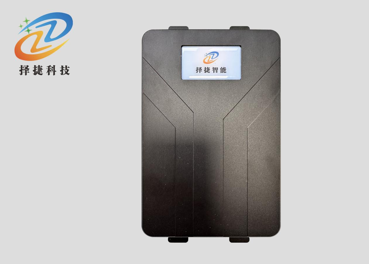
ZJF002-4A 4-Channel UHF RFID Reader
Model: ZJF002-4A
Specifications
◆ Frequency: GB 920 MHz ~ 925 MHz, GB 840 MHz ~ 845 MHz, FCC 902 MHz ~ 928 MHz, ETSI 865 MHz ~ 868 MHz, JP 916 MHz ~,920 MHz
◆ Selectable output power: ≤33 dBm.
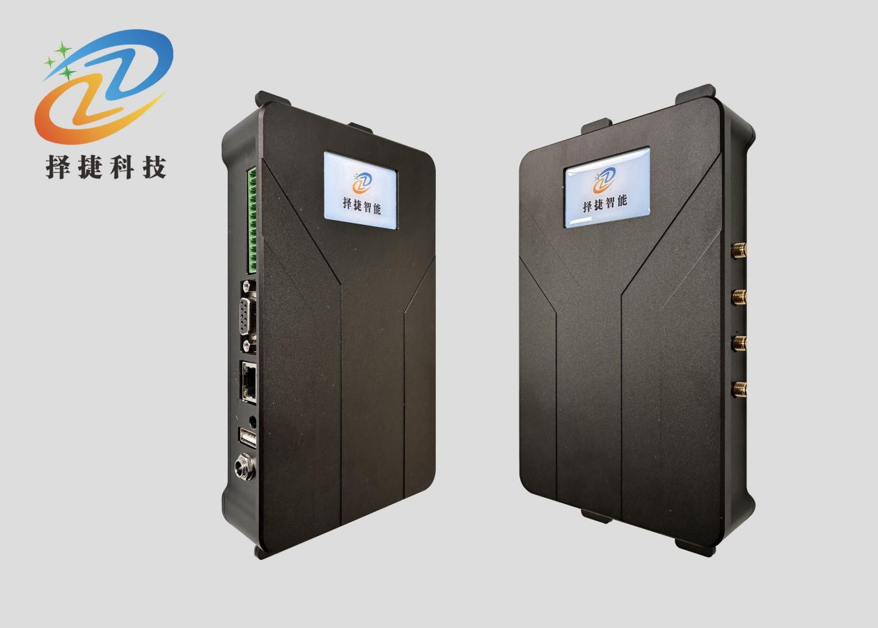
External interface: Standard RJ45, RS232, custom-service WIFI, POE, RS485, 4G
• Working mode: Wide-spectral FM (FHSS) or specified frequency, software settings
• Read card distance: 0-15m (associated with label)
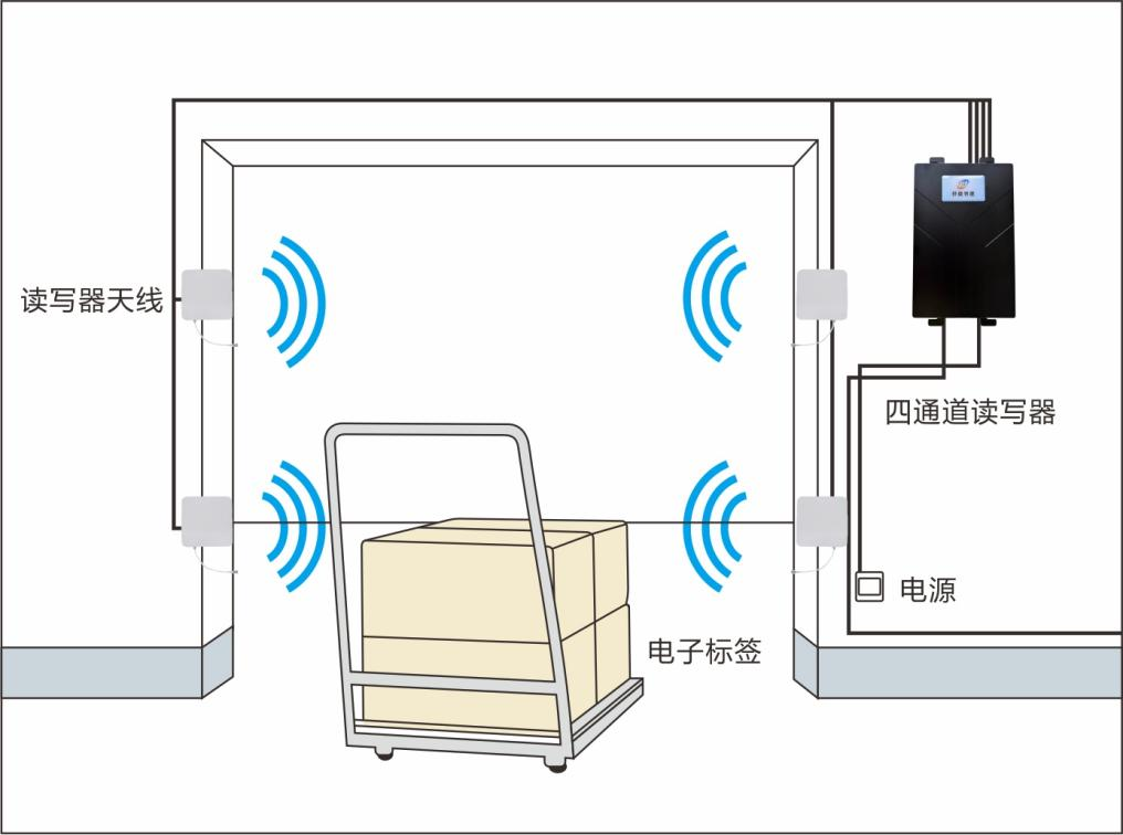
• Antenna: 4 9dbi round polarized antennas
• Working environment - working temperature: 20 - + 70°C
• Working environment - Storage temperature: -30 - +80°C
• Working environment - Atmospheric pressure: 86kPa ~ 108kPa
• Working environment - Humidity: 5-90% RH no condensation
• Dimensions: 224*116*33mm
• Rich communication interfaces: RJ45, RS232, customised for Bluetooth WIFI, POE, RS485, 4G
Additional Specifications
| Agreements | ISO/IEC18000-6C / IEC18000-6B /EPC C1Gen2 |
|---|---|
| Output Power | ≤ 33dBm |
| External interface | Standards RJ45, RS232, customise WIFI, POE, RS485, 4G |
| Working Mode | Wide-spectral FM (FHSS) or ad hoc frequency, software settings |
| Read card distance | Read distance 0-15m (associated with label) |
| Antenna | 4 9dbi round polarized antennas |
IV Electrical and mechanical parameters of antennas
Electrical performance
• Frequency range (Frequence Range): 902-928 MHz
• Gain: 9dBi
• Polarization: round polarization
◆ Semipower angle (Baam Width): Hor:68° Ver:68°
◆ Voltage standing wave ratio (VSWR): ≤1.3.
♪ Impedance: 50 times
◆ Front-to-back ratio: ≥13 dB
◆ Power (MAX.Power): 50W
◆ Axial ratio: ≤2dB
Lightning protection: straight-on-the-ground
Mechanical performance
• Connéctor: N-Female
◆ Connéctor position: Bottom straight out
• Antenna size (Dimension): 25825845mm
Net weight (Antenna weight): 0.58kg
◆ Effective wind loading area: ≤0.2 m²
• Raded wind resistance: 36.9 m/s
• Radiation material (Reflector material): aluminium
@RadomeMaterial: ABS
Zoome antenna colour (Radomcolor): White
Working temperature: -40 ~70°C
♪ Mounting Hardware: 30-50 mm
V Interface Definition
Quote the number, quote the definition, description.
1 OUT RI Relay 1 output R-end control signal
2 OUT L1 Relay 1 output L-end control signal
3 OUT_R2 Relay 2 output R-end control signal
4 OUT L2 Relay 2 output L-end control signal
5 INPUT_1 light & 1 input control signal
6 INPUT_2 light radium 2 input control signal
7 IO_GND I/0 input control signal power negative pole
8 RS485A RS485 Signal A
9 RS485B RS485 signal B
10 GND power negative pole
11 WIGO for root output signal 0 (to be customised)
12 WIG1 Bottom Straight Out for Root Output Signal 1 (To be Custom)
VI Product Presentation
 Ms. Lei
 Mr. Pang